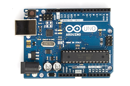
 A few months ago, I picked up an Arduino UNO plus an Ethernet Shield, and my addiction to digital electronics was rekindled (after a 15 year hiatus). When the annual "Decorate your Door" contest was announced, I decided that it was time to give up on "artistic creativity" and go for all-out-geek.
Our company mascot is a flying robot named Otto, which seemed like the perfect target for an "upgrade" using the Arduino and a bunch of tri-colored LEDs.
To drive the LEDs I chose the TPIC6B595 Shift Register, because a "standard" 74HC595 is limited to 70 milliamps (or so). The LEDs are the Betlux brand, and its spec sheet says that they'll happily eat 30 mA per color - which means that it can take 90 mA when they're showing the color white. That alone is enough current to fry the 74HC595.
Since the shift-register is a "current drain", the LED's anode (ground-pin) has to be connected to the shift-register. This leaves two approaches when designing the LED driver circuit:
- Use common-cathode LEDs, and connect each LED-color's anode to a pin on the shift-register to "drain" the current. We'll call this the continuous-power approach.
- Use common-anode LEDs, and connect that common-anode to the shift-register, and then use three PNP transistors to supply current to each of the LED's color-cathodes. This means that the CPU will have to continually cycle through the three colors (showing one at a time). We'll call this the Persistence Of Vision (POV) approach.
There are pros and cons of both approaches:
| Continuous Power | Persistence Of Vision | |
| Shift registers required | Three: One for each LED's color-anode pin (24 total). | Just one, connected to the common-anode of each LED package. |
| Arduino pins needed | Three: Connected to the shift-register pins SRCK, RCK, and SER_IN. | Six: The same three, plus a pin to select each color (Red/Green/Blue). Technically, you could use a 74139 de-mux and get by with just 5 Arduino pins. |
| LED Power consumption | When all 24 LEDs are lit up, 30mA * 24 = 720mA | Since only 8 LEDs are lit, 30mA * 8 = 240mA |
| Software "complexity" | Less: The Arduino only needs to transmit bits when the colors change. | More: The Arduino has to constantly refresh the display, either by using a continuous loop, or a software-interrupt timer. |
I opted for the power-hungry approach - that way, if the Arduino's software should happen to lock-up (unlikely, but possible), the display will continue to show the current colors. If I was going to build a bunch of these and chain them together, then I'd have to opt for the POV style.
Implementation and Construction
 The first step was to build the whole thing on the breadboard and make sure that it would actually work (yes, that's a 20 year old Jameco breadboard). I used my ammeter to measure the current coming through the LEDs and found resistor values that throttled the current to 20 mA, which helps reduce the overall power consumption (and may help extend the life of the LEDs).
 Once I had the software figured out, it was time to transfer it to a real board. I have a personal preference of never soldering ICs to boards, because something inevitably happens (either while soldering or static discharge) that requires replacement of the IC. I also chose to use a 25-pin connector to attach the LED driver to the project, even though it adds a whole bunch of extra soldering, it's nice having the freedom to detach the LED driver board (and re-use it on a future project).
  I took a 12x18 color printout of Otto, and started surgery with an old set of X-Acto knives. I cut out the regions that I wanted illuminated, and covered the holes with parchment paper to act as a diffuser. Six of the LEDs will reside behind the parchment paper, and the other two will be used for the eyes.
 I chose the clear-package LEDs because the datasheet says that they're brighter than the clouded ones - and brighter is always better, right? Well, not really. The catch is that the clouded ones will blend colors better (when making colors like yellow). So I built a reflector assembly for the six LEDs using a paper-towel tube, a tuna-fish can, and some aluminum foil (and lots of transparent tape to prevent the foil from shorting out the leads on the LEDs).
 After a few nights of late-night soldering, and then double-checking everything with my multi-meter to make sure nothing was shorted out, here's the assembled view of the completed project. (Yes, that's a cereal box.)
I powered up the project, ran it through the color-diagnostic test, and miraculously it actually worked!
Public unveiling

The Arduino stack is hanging on the wall behind the door. I powered it using a 1 amp iPod battery charger plugged into the Arduino's USB port, and I'm communicating to the Arduino via a very simple TCP/IP protocol that I devised (which also supports a Telnet session).

To control the lights and colors, I send commands to the Arduino which indicate the color (red, green, or blue), and then eight bits to specify which LEDs to illuminate with that color. Here's a map that shows where the eight bits reside within the project. Thus, to illuminate the two hands in a blue color, I would send the command "b10000001". The Arduino shifts the updated RGB bytes to the driver, and after sending the 24-bits, it triggers the RCK-pin on the shift-registers which "commits" the shifted bits.
Going one step further...

The light-show script is processed using a simple interpreter (also written in Java) that understands macros which are replayed some specified number of times. I'm sure a pro lighting tech could put together a more impressive lighting sequence, but as I already mentioned - I'm "artistically challenged"
I used Skybot Scheduler (yeah, shameless plug) to initiate the sound and light sequences. It also helped avoid problems with multiple people requesting songs simultaneously. I coded up a simple front-end web-page that I could display on a tablet (because anything that's "tablet enabled" makes it 10 times cooler - right?) The web front-end uses a Perl script to kick off the predefined Skybot job. Here's a video that shows the whole thing in action.
I think next year I'll try to incorporate some laser pointers with an Arduino stepper-motor controller, but I'm open to suggestions. Throw me a comment with your ideas for next year's project!
By the way, I won the "office door decorating contest" - score one for the geeks.