
In a previous blog post, I covered the details for a large-scale Illuminated Zapier display, which consisted of 248 tri-colored LEDs that were controlled by NodeJS on a Raspberry Pi.
One of my co-workers mentioned that it would be neat to have a smaller version of the display, which seemed like a great idea for a future project.
The theory/plan:
In May 2017, I started sketching out the possibilities:
When working out the math, it seemed that the quantity of LEDs per arm should be something like 5, 6, or 8. When I searched around for the available options for LEDs, the best fit appeared to be the Adafruit DotStar 144 LED strip. That would give me 6 LEDs per arm, and 8 arms per display, which is enough to build 3 full Zapier mini displays (6 x 8 x 3 = 144).
The next part was figuring out how "miniature" I could possibly make things. Rather than building a custom Pi Hat (that would stack on top of the RasPi), I wanted something that would plug into the RasPi, without adding too much additional (stacked) height.
The best approach was a Raspberry Pi Zero W, and then connecting it with a custom-designed board that would drive the LEDs. The dilemma was choosing stacked-headers, or right-angle connectors?
The advantage of stacked-headers is that the two rows of pins on the RasPi would line up with the pins on the custom board - whereas the right-angle headers causes things to connect up a little differently (outside rows versus inside rows).
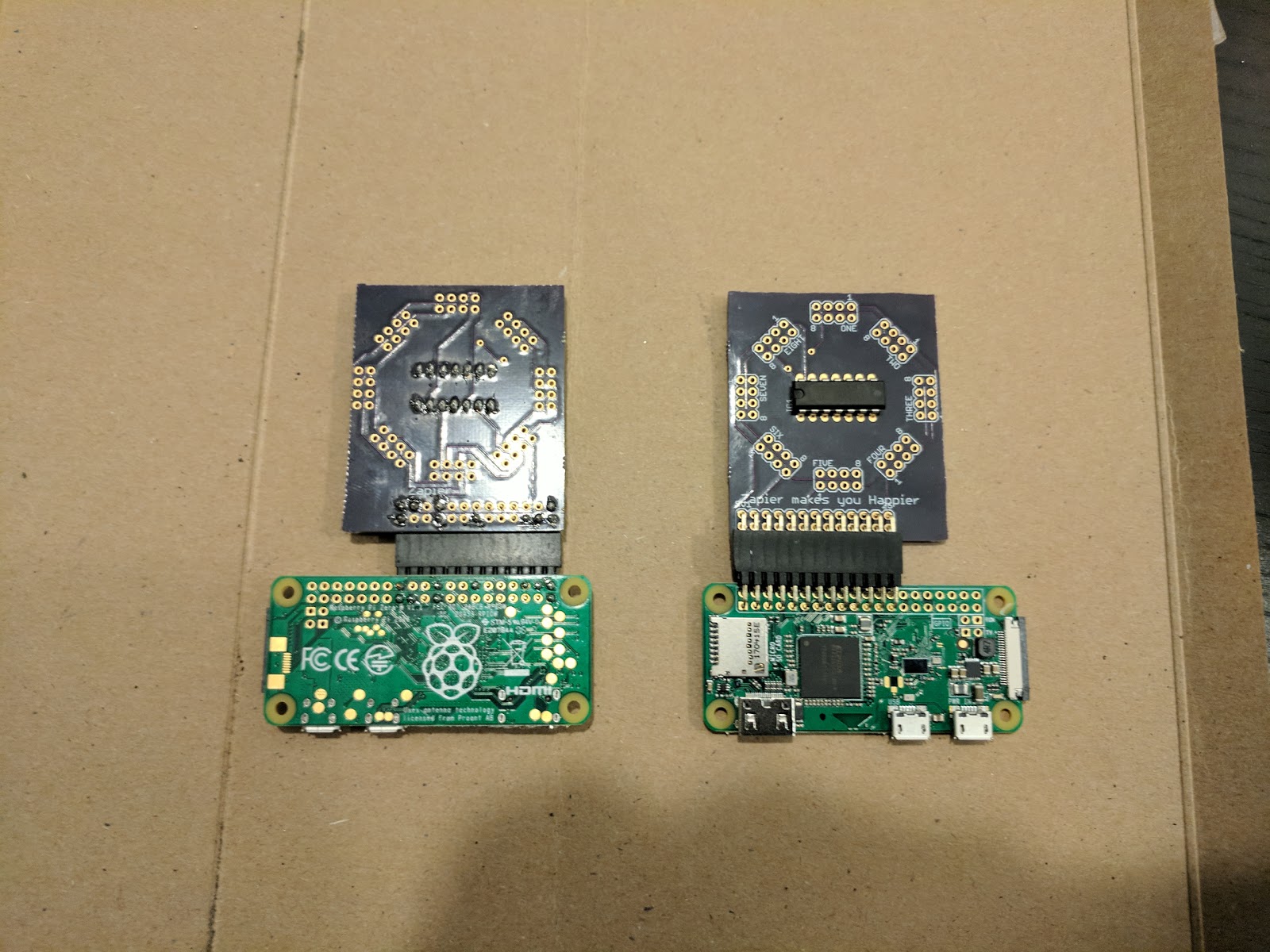
In the end, I went with the (more complicated) option of using right-angle headers/connectors, so that the RasPi and custom board would lay flat together:

After each round of design and planning, I would print out the custom board's layout onto a sheet of paper, punch holes for all of the connectors, and lay out the components, in order to assess the spacing and physical dimensions. This helped me avoid any pitfalls where the connectors would end up being "too close" and preventing things from being assembled correctly.
I used Autodesk's EAGLE software to design the schematic and layout of the custom board, along with lots of help and learning from some tutorials over at SparkFun. That resulted in the following layout:

When my paranoia was mostly-satisfied that I had all of the custom board's holes and traces/connections arranged correctly, I sent the design off to Osh Park for fabrication. Their service sent back three copies of the completed board, which matched nicely with the quantity of LEDs that I had from the LED strip.

Some Assembly Required
When all of the parts arrived, the first step involved lots of time with a hacksaw, cutting the board apart, and also cutting up the connectors/headers into the specific sizes:
Then lots of long hours with a soldering iron, getting the connectors installed onto the RasPi and the custom board:
One of the unexpected and most difficult challenges was soldering the LED strip segments. In my previous project, cutting the LED strip resulted in a full-circle of solder pads on each segment/strip. Unfortunately, the high-density LED strip only provided a single solder pad in between each LED - thus when cutting apart the strip, I only had a half circle to use for soldering:


Eventually, I was able to solder (and re-solder) enough of the connections to get a few arms working correctly:

And then finally had the finished products:

Lessons Learned
The most difficult part of this project was the assembly/soldering of the LED strips onto the arms - and it's the most brittle part of the project.
When I started this project, there weren't any options available at the time. Shortly after I started building this project, I discovered the Blinkt product/project, which would likely make the construction less tedious - but would require a larger board, with bigger connectors, and a 3 to 8 demultiplexer (74138 or 74238) along with some custom software/driver tweaks. There's always a trade-off in these types of projects.
Additional Info
Here are more photos of the construction process.