 Since I'm usually a month (or more) behind on my blogging, here's my story.
Back in 1998, my dad happened to have a bunch of dual-color LEDs, consisting of Green and Red (and thus, Yellow when both colors were illuminated) that he no longer needed. When I counted them out, there were just over 60 LEDs present - which made me wonder if I could build a clock?
I had spent too much time building all kinds of fun things using various forms of the 8051 microcontroller, and since I had the EEPROM burner and UV eraser in my home lab, it was the best fit for the project. (These days, I'd much rather use an Arduino or something).
Since a clock would require 60 individually addressable LEDs, along with two individually addressable colors, that equates to a lot more pins than what's available on the 8051.
Multiplexing to the rescue!
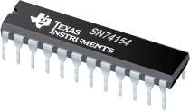
 I'm a huge fan of multiplexers (and serial shift registers). In this case, I took the 60 LEDs and divided them into four quadrants. I could use two pins to select a quadrant, and then use four pins to select 16 different possible LEDs within that quadrant, using the 74154 4x16 demultiplexor. Throw in the two pins needed for the color selection, and I could drive all of the necessary data signals with eight little bits!
Since I had a few extra data pins available, I hooked up a few push buttons. Two are to set the minutes forward/backward, and two are to set the hours forward/backward. There's a fifth button, but I don't remember what it does. Maybe some day I'll find the old assembler code I wrote for this project, and see if there's any mention of its purpose.
Assembly
Any true hacker's project rarely comes in a "polished/presentable" case. So the next question was what kind of packaging to use for housing this project? I needed something round, and a large enough size to house a custom circuit board that I made. I thought of a frisbee, but they weren't deep enough for all of the wiring (done by hand - ugh!). The next best candidate was an ol' fashioned pie tin! After stuffing everything inside it, I used a piece of wire mesh to hold everything inside it.
Final result
Here's the "internal view". The 8051 is the big 40-pin beast in the middle (with electrical tape covering the UV-EEPROM window). The push-buttons are just above the CPU. The 74154 is in the top-right corner. There's a bunch of 7407 inverters spread around the perimeter, which are used to drive the LEDs (common cathode/ground), along with a pair of transistors that supply the red/green anodes on the LEDs. Yes, I used to have a lot of spare time back then.
Action shot: The clock displaying the time 3:01:36 o'clock.
Semi-useless video clip:
I'm really thankful I never brought it into school for "show and tell". What's your favorite geeky clock? Leave a comment below!


No comments:
Post a Comment